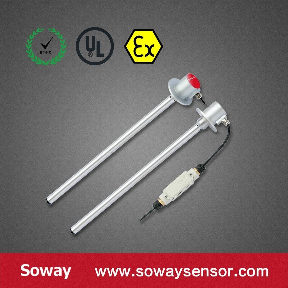
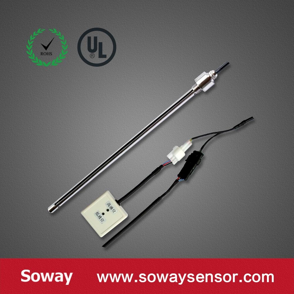
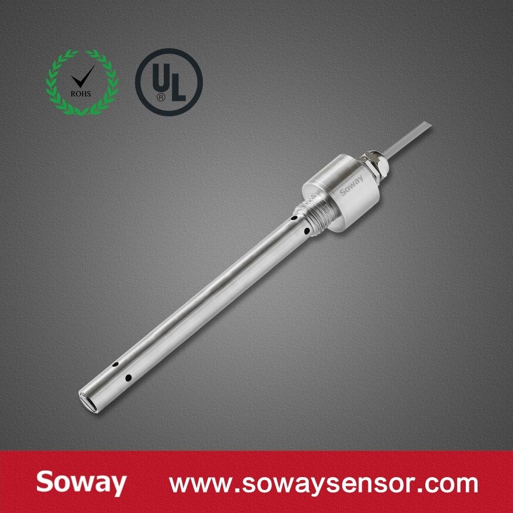
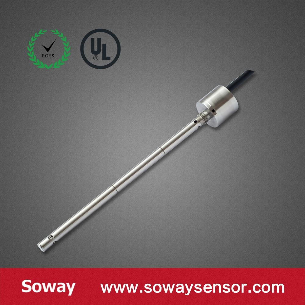
Capacitive Fuel Tank Level Sensor for trucks

Model No.︰soway
Brand Name︰soway
Country of Origin︰China
Unit Price︰-
Minimum Order︰1 pc
Product Description
Performance parameters:
- Power: DC 5V、12V,9~28V
- Displacement range: 100 to 2000 mm
- The output signal: 0-5 VDC ,4-20 mA ,Canbus,RS232, RS485 etc.
- Digital RS485/RS232 output
- Linear error: analog output:± 0.1%F.S.
- Working temperature:-25 ℃-+ 85 ℃
Application:
1,tanker, automobile fuel tank
2, the steel industry
3, metallurgical industry
4, oil field, chemical industry
5, the conductive liquid measurement
Introduction
- This article is intended to introduce capacitive level sensor installation,commissioning and calibration procedure.
Please read this manual carefully, complete the installation according to the instructions correctly, especially comply with the relevant national compulsory safety standards.
When do not implement the above requirements and cause any equipment damage or personal injury, the manufacturer will not be responsible for these.
Wiring way and port description
2.1 Interface and Wiring
Analog signal-Voltage / Current output : +VCC,GND,VOUT / IOUT
Digital signal-RS485 communication::+VCC,GND, A, B 2.2 Wiring Port DescriptionSeries No.:
Item Definition Thread Color 1
+VCC
Power supply Typical value
Red
2
GND
Power Ground
Black
3
A
RS485 TR+
Blue/Yellow
4
B
RS485 TR-
White
5
VOUT
Analog voltage output
Blue
6
IOUT
analog current output
Blue
Definition:
1.Output is only one way output, so it has the same cable color.
2.This wiring is standard cable colors, please reference to the actual description if difference.
*If the current output does not reach the full-scale,it requires external loop load resistance.2.3 Wiring diagram
Voltage output wiring diagram: Diagram for three wires current output wiring: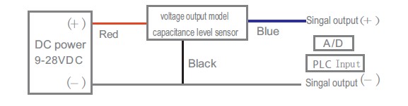
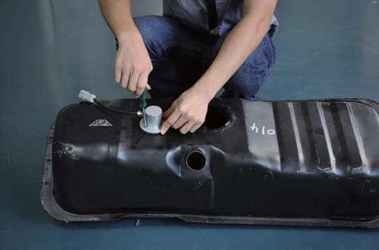
3.Sensor Installation Steps
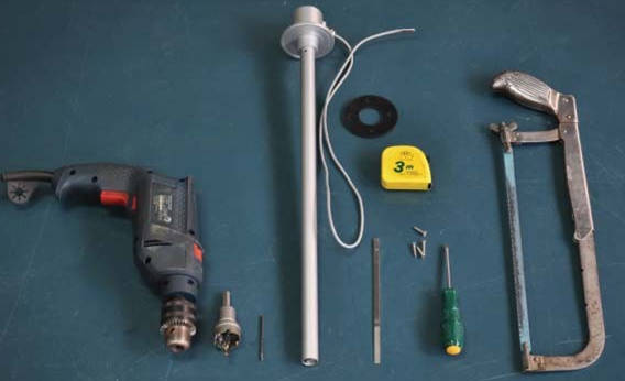
3.1 Basic tools as following:
3.2:Drilling
3.2.1 First, clean the tank residual oil, then rinse with water many times to make it looks best
3.2.2 To select the drilling point on the center of the oil tank surface,and please consider that wether it conflict with the tank inside unit.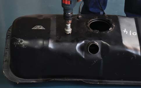
3.2.3 Use hole saw to drill point on selected fixed point ,when drilling ,please avoid the iron filing falling into the tank.
3.2.4 When completed, according to sensor gasket holes,select a smaller drills to process fixing holes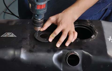
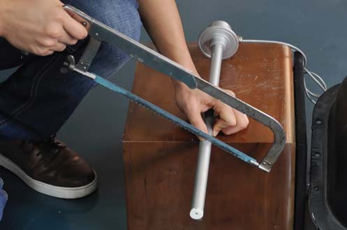
3.3 Sensor truncation
3.3.1 First, measure inside height of the tank, get the value H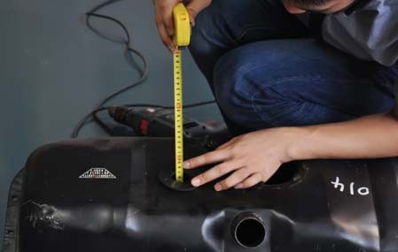
3.3.2 The inside height of the tank H - 10mm = L (L is the sensor height from flange lower end portion to the bottom)
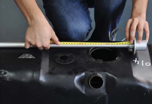
3.3.3 After get value L,then use a hacksaw to saw off the excess part of the sensor
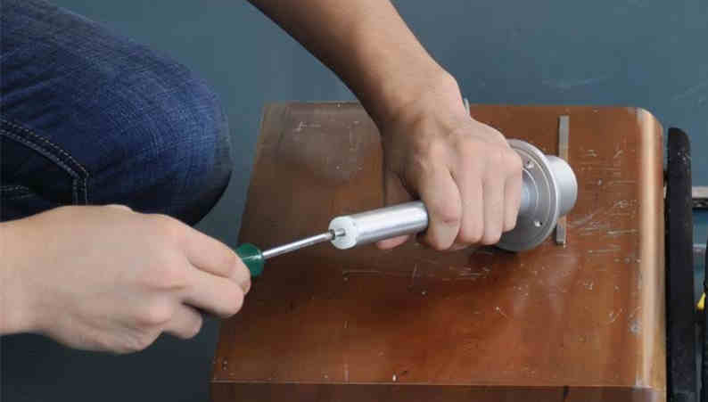
3.3.4 After sawing off, using grater to clean the surface fines, maintaining surface smooth and clean, more,cleaning
out the inside and outside aluminum scrap.
3.3.5 Re-fixed the bottom terminal with screws,now the sawing off is over
3.4 Calibration
Note: 1.When the sensor is truncated, you must re-calibration
2.Calibration process only related with immersion liquid height, immersion medium ,and has nothing to do with the fuel tank capacity
3.4.1.Analog output calibration method
3.4.1.1 Before sensor calibration,please confirm the sensor is properly connected with the handheld calibrator (Attachment is
handheld calibrator specification),then turn on the calibration power switch,meanwhile prepare the number of necessary measuring medium(The container depth should be bigger than the sensor range )
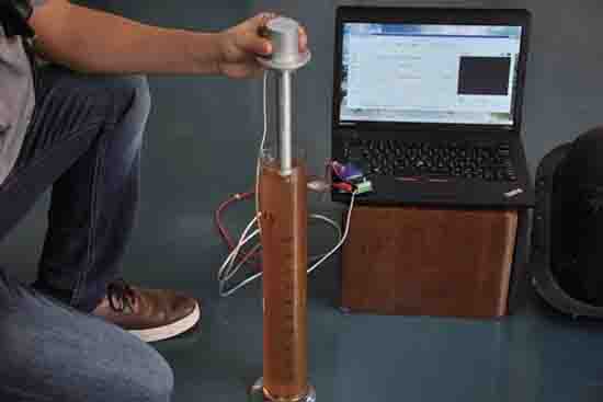
3.4.1.2 Fixing the sensor, the height of the immersed bottom fixed to the zero level of liquid that customer request.Stand for
10 seconds,press the button on the zero point calibration,when the lights flashed, which indicate successful zero calibration.then the output 0V or 4mA.(That is zero-bit output)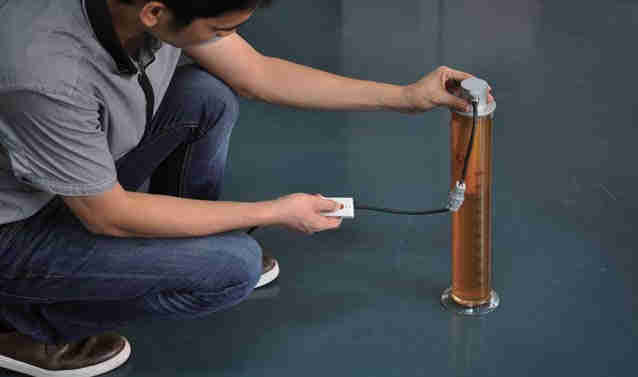
3.4.1.3 Similar to step 2,compare the height of the sensor immersed to full-scale liquid height set by the customer,and let stand for 10 seconds, press the full-scale calibration button, when the light flashed, it represents the full-scale calibration success, then the output 5V or 10V, 20mA(This is full-scale output)
3.3.4 When both zero and span calibration succeeds, you can move the sensor in the level upper and lower by hand-held then you can see the display instrument changes with the level changes accordingly.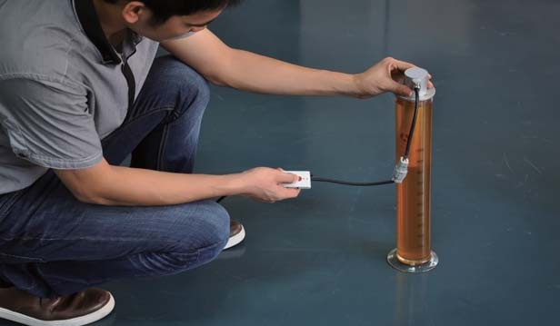
3.4.1.4 When both zero and span calibration succeeds, you can move the sensor in the level upper and lower by hand-held then you can see the display instrument changes with the level changes.
Exception Specification:
When the sensor continuous output 2.5V or 5V, 12mA, it means abnormal sensor calibration,then must be calibrated
after power restart
3.4.2 Digital output calibration method
3.4.2.1 .please make sure the sensor has connected the power before calibration,and the digital output lines connected to the computer through the adapter, and turn on the test software(see the relevant documentation for software operation)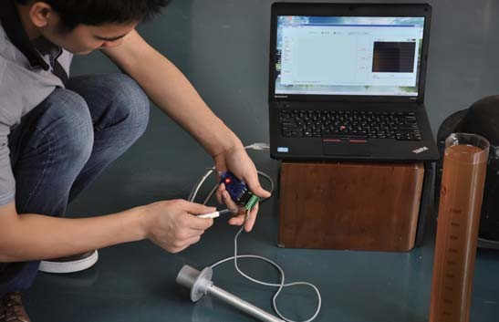
3.4.2.2 Please make the bottom of normal connected sensor immersed to the desired zero point,let stand for 10 seconds, and make the operating software record zero value;
3.4.2.3 Similar to step 2,make the sensor immersed to the full-scale,let stand for 10 seconds,and make the operating software record zero value;
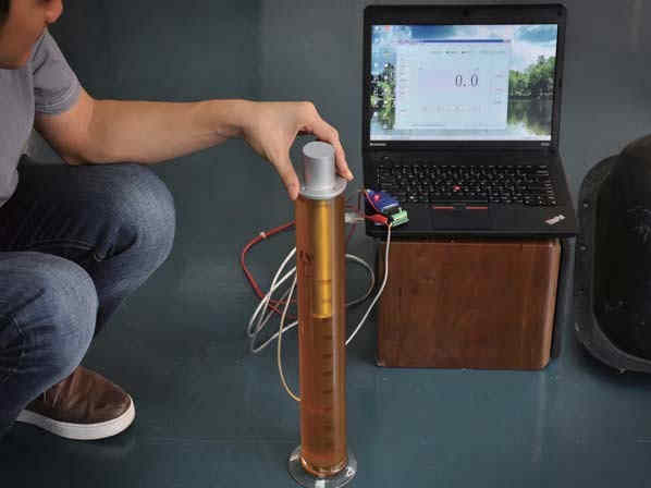
3.4.2.4 According to the procedure of software calibration success,Open the display interface, you can see the display interface data changes with the height of the sensor immersed;
Exception specification:
When the software displays the calibration is unsuccessful,you must be calibrated after power restart.
3.5 Installation and mounting
3.5.1 When the calibration process ends normally, you can install the sensor in the fuel tank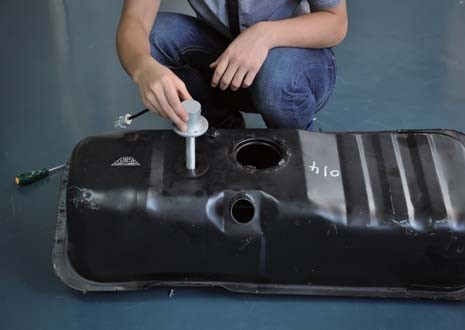
3.5.2 Now you can mount the sensor on the fuel tank by by self-tapping screws ,thn the installation process is finished
Attached:List of tools required for installation and calibration
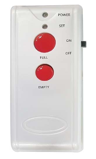
1.Make the handheld calibrator connector connect with the sensor output connectors,slide switch on the right side, placed ON, the POWER light;
2.Adjust the liquid level to the zero position,then press EMPTY button for nearly 2 seconds until the SET leght shining one time,mean zero calibration success;
3.same as above,adjust the liquid level to the full position,then press FULL button for nearly 2 seconds until the SET leght shining one time,mean full calibration success;
4.After that,release the Calibration device conecotr,then follow the wiring method;
Note: the calibration process must be completed together, in the process can not power outage; If calibration output abnormal, please follow the steps to calibration.
Product Image